
2026-08-10 Proposal for a supplement published for comment.
Index
- 1.0 Introduction
- 2.0 Frame and Legs
- 3.0 Track
- 4.0 Wiring
- 5.0 Control
- 6.0 Scenery
- 7.0 Glossary
- 8.0 Revision History
- File Attachment
Legend
IM -S x.y, where x. and y are number – example: MM-S2.15
IM -RP x.y, where x. and y are numbers – example: MM-RP 5.11
IM -FAQ abx.y, where ab are S or RP, and x. and y are numbers – example MM-FAQ S1.7, MM -FAQ RP3.2
IM -S = Standard. All Free-mo modules and participants must conform to the requirement/standard stated.
IM -RP = Recommended Practice. These are procedures or specifications which are strongly encouraged for maximal reliability or fidelity.
IM -FAQ = Frequently Asked Question/Answers which explain the reasoning behind a particular Standard or Recommended Practice. Free-mo FAQ Page.
1.0 Introduction
IM-S1.1 Free-mo Modules fall into four basic categories, see S1.5. This document is a supplement to the “The Official Free-mo Standard“. Listed here are the variations and exceptions to “The Official Free-mo Standard” for Industrial Modules. Industrial modules must meet all of the “The Official Free-mo Standard” with the variations and exceptions listed below. This document works in parallel with “The Official Free-mo Standard” and is incomplete without it. When there is a gap in the numbering see “The Official Free-mo Standard“.
IM-S1.2 “Free-mo modules not only provide track to operate realistic models, but also emphasize realistic, plausible scenery; realistic, reliable trackwork; and operations” (S1.1). “The Official Free-mo Standard” is written for Mainline trackwork. Not everything in the prototype is mainline trackwork. The Industrial Standard were developed as a standard for industrial prototype locations.
Industry-mo – Industry modules represent Industrial districts. Industry modules have restrictive track with limited clearances and smaller radius curves and are not designed nor intended for Mainline or Branchline traffic except to other Industry-mo modules. (FAQ-IM-S1.2)
IM-S1.3 The Industrial Standards are a subset of “The Official Free-mo Standard“. Most Free-mo setups are Mainline setups. If you build to the Industrial standards your setup opportunities might be limited. Industrial modules are intended to be off a junction or at the end of a branch of the Mainline or Branchline modules. If you build a module to the Industrial standards, you need to inform the run chief that you module is a Industrial module when you submit it for possible inclusion in a setup.
2.0 Frame and Legs
IM-S2.2 Single-track endplates shall be either 18 or 24 inches wide by 6 inches tall
IM-S2.3 Double-track endplates, there is no provision for double track endplates in Industrial-mo modules.
IM-S2.4 Roadbed shall be 1/8 inch cork or equivalent on 1/2 inch plywood or equivalent. Foam tops are acceptable if braced to prevent sagging or flexing.
IM-S2.12 Alignment Pins – Alignment pins are optional. When an Industry-mo module employs alignment pins, those pins must conform to the Speed-mo pin standard. (see IM-7.0-Speed-mo-Pin-Standard, IM-S3.7)
IM-S-2.12.1 – If installing pins, the module owner is responsible for providing some mechanism to be able to connect to a module that does not have pins. Popular methods are: removable pins, one inch adapter module, “full size” adapter module. (FAQ-IM-S2.12.1)
3.0 Track
IM-S3.3 The through track shall be centered on the 18-inch or 24-inch endplate.(see IM-S2.2)
IM-S3.4 On Double-track modules, there is no provision for double track modules in Industrial-mo modules.
IM-S3.5 Track on the through route must be perpendicular to the endplate for 4.5 inches from each end of the module.
S3.6 Track on the through route must be straight and level for 4.5 inches from each end of the module.
IM-RP3.6.1 The points of a turnout should not be within 4.5″ of the end of a module.
IM-S3.7 Rails shall be cut flush with the end of the module. (FAQ-IM-RP-3.7)
IM-RP3.7.1 Industrial Modules use flush rails so rail joiners will not be needed or used between industrial modules. Between an IM and other modules will be code 70 to code 83 and a fitter rail would not work well . An adapter module of some kind is needed. (FAQ-IM-RP3.7.1)
IM-RP3.7.3 Industrial Modules use flush rails so rail joiners will not be needed or used between industrial modules. Between an IM and other modules will be code 70 to code 83 and a fitter rail would not work well . An adapter module of some kind is needed.
IM-RP3.7.4 Cut the rails back 0.015″ from the end of the module. This will result in a 0.03″ air gap between modules.
IM-S3.8 Turnouts on the through route shall be at least #5.
IM-S3.9 There shall be a minimum of 9 inches of straight track between reverse curves.
IM-S3.10 Track on the through route of a Industrial module must ALL be Code 70 nickel-silver rail without exception.
S3.11 Sidings, spurs and other tracks of a Industrial module may be Code 70 or smaller, but shall be no less than Code 40.
IM-S3.12 The minimum permitted curve radius on a through route of a Industrial Module is 22 inches. This includes through track sidings and other tracks where through traffic will run.
IM-S3.13 Spacing between tracks on curves of a Industrial module shall allow for Class I equipment to operate without fouling each other; per NMRA Standards RP-11 Curvature and Rolling Stock – (3/2018). NOTE: That is the letter I not a 1 for the class.
IM-S3.14 Maximum permitted grade on the through route of a Industrial module is 4.0 percent (approximately 1/2 inch per foot). NOTE: Spurs and non-through route tracks can be greater than 4%.
IM-S3.15 Curves on the through route of a Industrial module shall be appropriate for Industrial operation of Class I Equipment see NMRA Standards RP-11 Curvature and Rolling Stock. NOTE: That is the letter I not a 1 for the class.
4.0 Wiring
There are no variations or exceptions in this section to the Free-mo Standards for a Industrial Modules.
5.0 Control
There are no variations or exceptions in this section to the Free-mo Standards for a Industrial Modules.
6.0 Scenery
There are no variations or exceptions in this section to the Free-mo Standards for a Industrial Modules.
IM-S6.3 Scenery at the Free-mo Industrial Module end(s) shall have a flat profile 1/4″ below the top of the rail on the through route.
7.0 Glossary
- Speed-mo Pin Standard refers to the Speed-mo Practices and Standards, https://www.speed-mo.org/standards-and-recommended-practices/, to the extent that those practices and standards relate to the installation and use of alignment pins. Its principal dimensions and geometry are reflected in this diagram. This diagram is for information only, a Speed-mo Template should be used for drilling the holes.
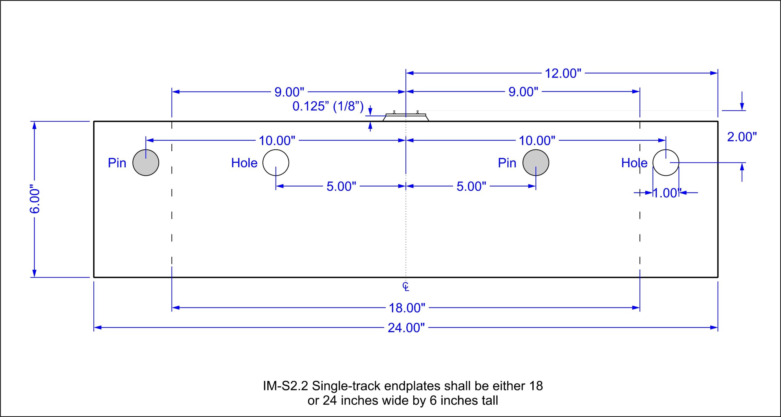
- Speed-mo Template refers to the template defined by the Speed-mo Practices and Standards. https://www.speed-mo.org/standards-and-recommended-practices/.
8.0 Revision History
Free-mo Standards & Recommended Practices Supplement for Mini-mo Modules Revision History
- 2026-08-13 “IM-S2.11 – Alignment Pins” number changed to IM-S2.12. S2.11 is in use in the main standards for consistency this was re-numbered to IM-S2.12.
- 2026-08-13 IM-S-2.12.1 this got omitted by accident, added as was decided by the group.
- 2026-08-10 Proposal added to the Free-mo Website and announced to the greater Free-mo community.
- 2024-04-05 Page created for development.